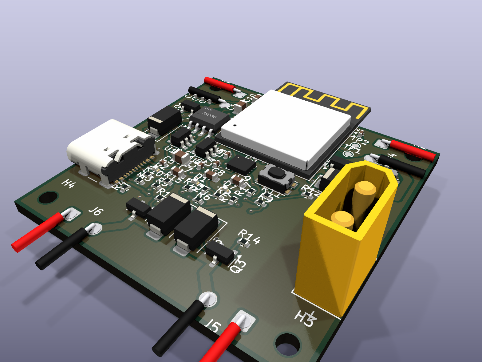
OHM-0009
ESP32-S3 Micro Quadcopter Controller — 6-layer, 40 × 40 mm
Design demo6 layersRev 029
- MCU
- ESP32-S3-MINI-1
- Input
- 1S LiPo via XT30
- Layers
- 6
- Size
- 40 × 40 mm
- Parts
- 61
- Assembly
- Single-sided
- Fabrication
- Not fabricated
- Physical testing
- Not physically tested
Shipping extra
01
Prompt
Original brief (condensed): ESP32-S3 micro quadcopter flight controller on an exact 40 × 40 mm, four-layer PCB. 1S LiPo via XT30, four brushed motor MOSFET drivers with flyback diodes, a six-axis IMU, USB-C charging, boot and reset buttons, and four M2 mounting holes. Size traces for up to 8 A total battery current.
Conversation edits:
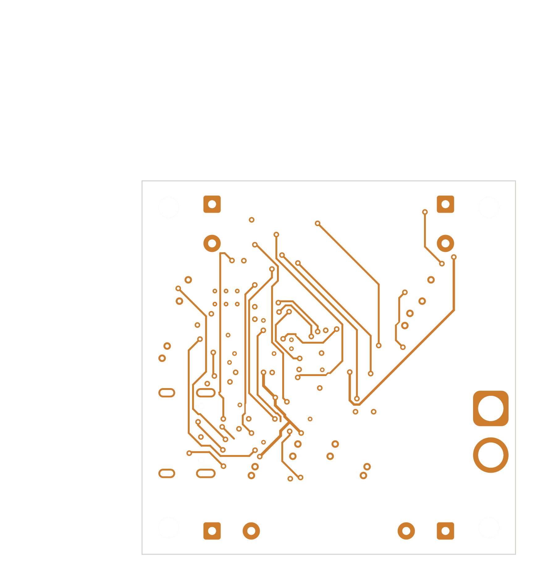
- Final routing was forced to six layers from the original four-layer brief.
- The LDO was changed to MIC5219; the inner VBAT plane was upgraded to 2 oz after the current check.
02
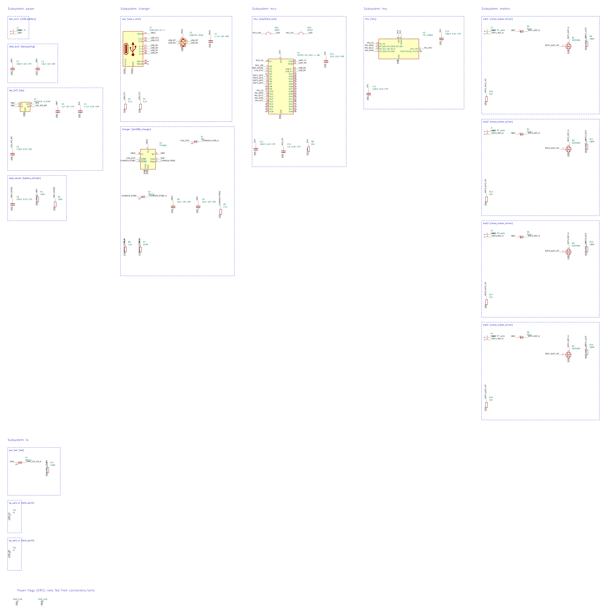
Schematic
03
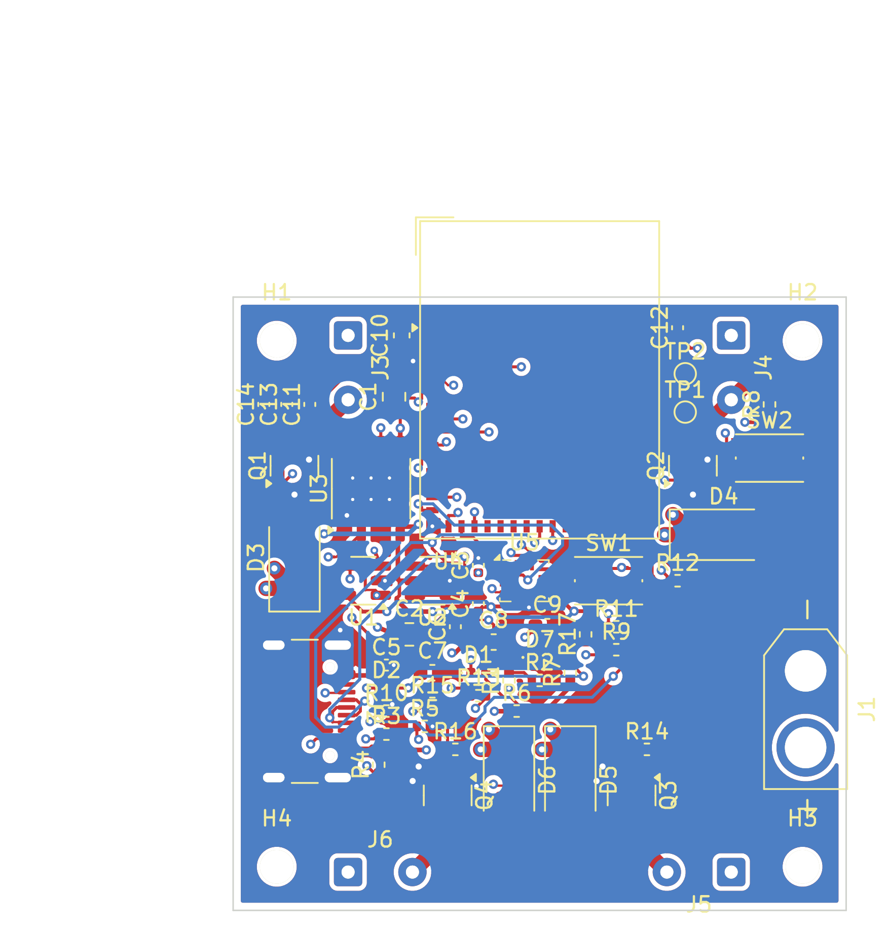
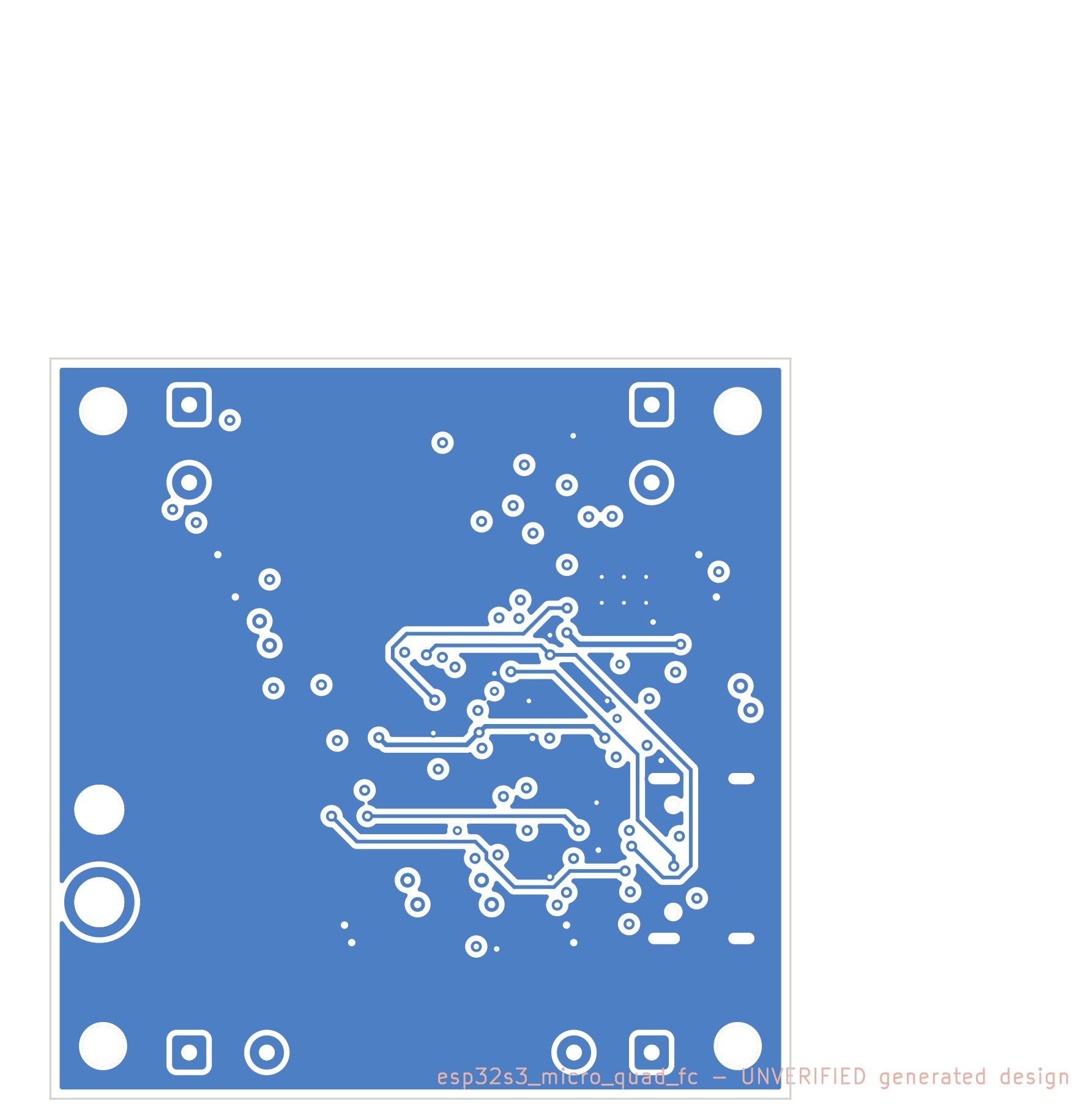
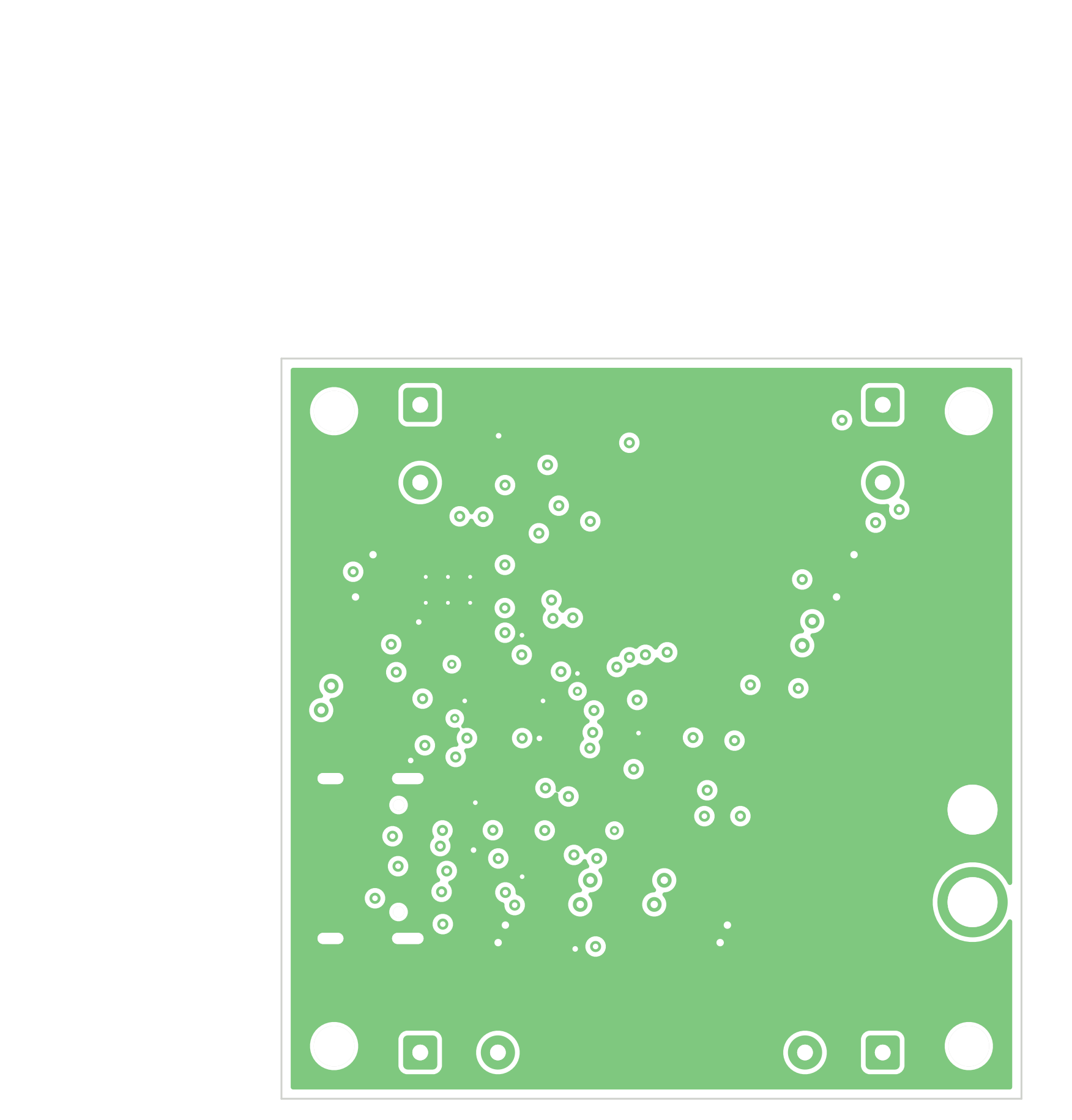
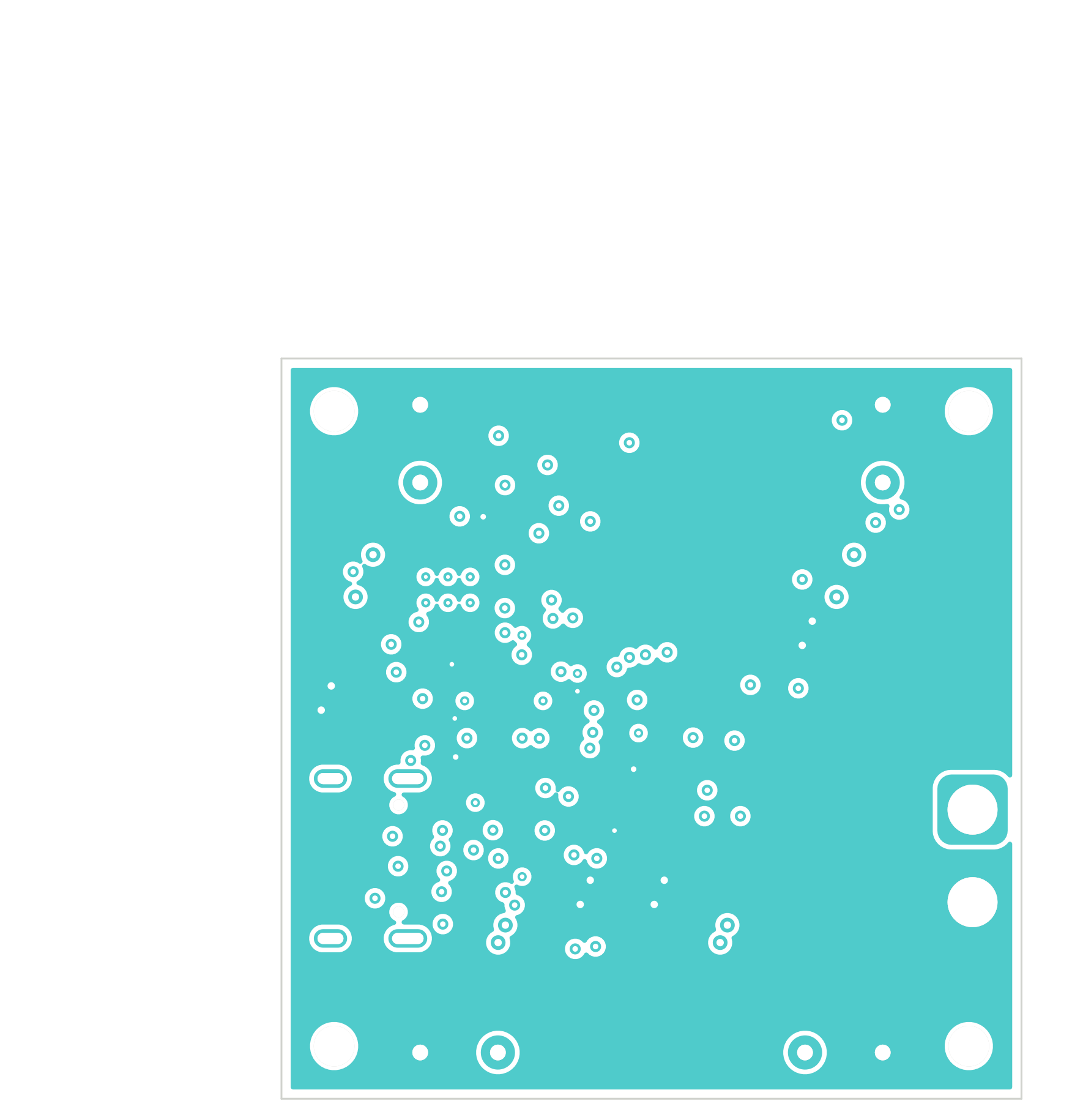
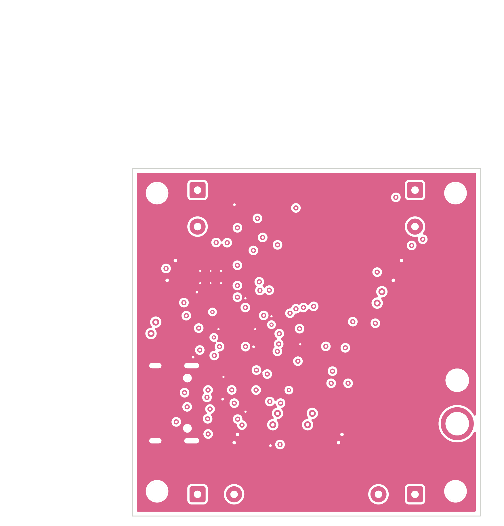
Layout & 3D
04
Key features
A generated six-layer, 40 × 40 mm controller for a micro quadcopter. It combines an ESP32-S3 module, SPI IMU, four brushed-motor switches, battery sensing and USB-C charging. The automated current check selected 2 oz inner copper for the VBAT plane. It has not been assembled or flight-tested.
- •ESP32-S3-MINI-1 and SPI six-axis IMU
- •Four brushed-motor MOSFET drivers and battery-voltage sensing
- •1S LiPo XT30 input and onboard USB-C charging
- •Six copper layers with a dedicated 2 oz VBAT plane
- •40 × 40 mm fixed outline with four M2 mounting holes
05
Notes
- Source: agent-pcb-mcp 0.7.1 run quad-fc3, board revision r029. Final summary and DoD: 0 unrouted, 0 DRC errors, 0 ERC errors; 91 DRC warnings remain. The generated REVIEW.md contains stale pre-repair routing warnings.
- The power-plane calculation gives a 2.12× margin at the narrowest VBAT neck for a 2.12 A branch with 2 oz inner copper; this is a calculated value, not a measured current test.
- Filled and capped via-in-pad fabrication, LDO dropout and heat, parts, footprints and IMU orientation all need human review. No motor, radio or flight test has been performed.
06
Files
This public case shows previews only. Contact us to order; manufacturing files are shared after payment.
Start from this board
Describe what you want to change and we'll generate a new design based on this one.